
For Mechanisms and Things That Move this week, Dustyn asked us to draw a Free Body Diagram for some common household object. Since I’ve been spending nearly every waking minute beside my camera shooting a stop motion animation, I chose my tripod.
What’s a Free Body Diagram? A Free Body Diagram portrays the forces acting on a system. To draw a Free Body Diagram you break your system down into a set of simple machines and use the laws of mechanics to analyze how the various parts of those machines balance each other. Drawing one lets you know how the variables in your system relate to each other: how the weight of one object might affect the necessary torque in a motor, or how the angle of a support might affect the kind type of fastener you use, etc.
To start off with, here’s a drawing of my camera on my tripod.

I made a drawing because, obviously, my camera was busy applying torque to the tripod. Now, here’s the Force Body Diagram:
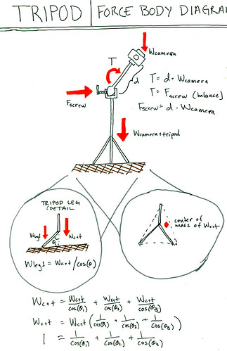
(View the large size.) There are two parts of the system I’m analyzing here. First, the screw which holds the camera in place at an angle at the top of the tripod. Second, the three legs that support the weight of the camera and tripod system. I’ll take the first part first.
The screw-system holds the camera in place at an angle by balancing the torque applied by the camera at the ball joint with the force from the screw which holds the ball joint in place. As you can see in the diagram, the torque is equal to the length of the shaft to the camera (in real life no more than a couple of inches) and the weight of the camera itself. The product of those two is the minimum amount of force the screw must be applying since the camera is currently aloft at quite the jaunty angle.
The second system, the tripod legs, has two things going on. First, the angle of each of the tripod legs serves to distribute a portion of the total weight of the camera and the above part of the tripod. Each leg’s angle lies at a vertex of a triangle between the leg, the floor, and the extended vertical line of the tripod’s shaft. The tripod’s weight is applied along that vertical line adjacent to the angle and we want to know the portion distributed to the leg, which makes up the hypotenuse of the triangle. Hence, the part of the weight carried by each leg is equal to the total weight divided by the cosine of the angle.
Now, let’s take this a bit further. Take a look at the three equations at the bottom of the diagram. We know that the sum of the portions for each leg added up to the total weight of the camera plus tripod system. If we do a little algebra, something interesting happens. The weight of the camera plus tripod actually cancels out of the equation. We’re left with a relationship between the three leg-angles themselves directly. This makes sense. The angle of each leg only determines what portion of the weight that particular leg bears, not the total weight its capable of bearing. As long as each leg is doing its share of the work, then (all other things being equal) they should be able to hold up the weight above them.
Another interesting observation falls out of this bit of algebra. The cosine of an angle decreases as the angle rise from 0 to 90 degrees. So, of course, the inverse of that cosine increases along that same range of angles. In other words, the further out you pull each leg from the tripod, the less of the weight that leg supports.
This might be a counterintuitive result since when we spread the legs out the tripod becomes more stable. That is due to a factor illustrated in the second inset in my diagram: when we spread out the legs, we make it more likely that the center of mass of the tripod plus camera system will be within the plane defined by the tripod’s legs.
Anyway, I’m sure this analysis is incomplete. One of the main experiences of making this kind of diagram is that the more you put into it, the more you think of to put into it. And part of the art is choosing when to stop.