
Ever since I was a kid, I’ve gone through intermittent periods of being obsessed with Etch-A-Sketches. The last such period was in 2005. There was an Etch-A-Sketch resident in the French pastry shop where I worked at the time and so I’d doodle with it at slow moments, eventually buying one for home use and making a whole series of drawings.
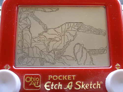

There’s something about the continuous trace and physical scratching of the Etch-A-Sketch point that satisfies both the primitive and sophisticated sides of the drawing urge: like using high tech remote manipulator arms to scratch pictures in the dirt.
Hence, when a recent Drawing Machines assignment directed us to build a “simple” physical drawing machine, my mind immediately returned to the Etch-A-Sketch and the elemental control it gives you over the minute up-down/left-right movement of the drawing point. I decided to try to see if I could transfer the Etch-A-Sketch’s combination of primitive and sophisticated effects to a drawing machine that operated more at the human drawing scale of a real pen and paper.
The result was a two-axis drawing machine built with stepper motors scavenged from CD-ROM drives.

I started by pulling two CD-ROM drives off the ITP junk shelf. Last week, I had help from Todd Holoubeck and Tom Igoe understanding how to control stepper motors, so I figured out pretty quickly that these motors were bipolar steppers (they each had four contacts).
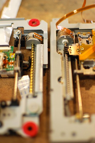
Once I knew that, I tested the resistance between the contacts on each stepper to identify the pairs of leads that were actually connected. I attached each of these pairs to half of an h-bridge and programmed the Arduino to step them as slowly as possible (using the Arduino Stepper library). Switching the polarity of each lead-pair around until the motor moved in a straight line showed me exactly how the motor needed to be plugged in for full control from the Arduino. Here are short videos of each of the motors moving under control of the Arduino:
Once I’d gotten control of the motors, I set about designing a mechanism for translating the movement of the two motors into x/y control of a pen.
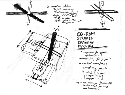
The trick was to get both the motors mounted at the same height around the middle of the pen’s length and to attach extensions to them that could hold the pen tightly while not limiting its movement along the other axis. After some early experiments, I settled on cutting rectangles out of flat pieces of masonite, which would allow the pens to slide in one axis while constraining them in the other:
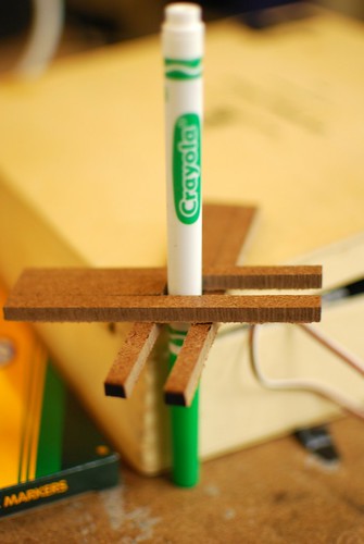
After cutting out these masonite pen holsters, I hot-glued them to the motors, which I’d mounted on pieces of two-by-four in order to get them to a good height around the middle of the pen. Once I had the whole arrangement in place, I hot glued it to a wooden base piece to keep it all in delicate alignment. Here you can see it all setup and doing a test pattern of movement:
Then, finally, I attached two pots to my Arduino and programmed it to detect the change in direction of each pot and reverse direction along the relevant axis (see the complete code in the embedded gist at the bottom of this post). I ran into a bit of trouble when the steppers would get all the way to one side of their range. They each have built-in mechanisms to prevent jamming and motor burn out at that point so they can soak up attempts to move too far in any one direction, the result being that the range of motor motion covered by the knobs’ rotation would get shifted off to the side whenever the motor went all the way to one side of its range. So, I added an extra bit of logic to the sketch that had the motor continue to move in a given direction if the knob seemed like it was turned all the way (i.e. its reading was near 0 or 1024). This let you escape the kind of stuck situation that would otherwise arise from the steppers’ anti-jam hardware.
The final device ended up embodying the aesthetic properties of the Etch-A-Sketch I described above in a surprisingly effective way. Sometimes, when the pressure between the pen and the paper was perfect, the motion control would be smooth and precise, enabling me to make much straighter lines and cleaner right angles than I ever could by hand — just the kind of sensation of precise control provided by the Etch-A-Sketch.
At other times, when the pen would get torqued into a odd angle, one of the motors would vibrate at the edge of its range, or the pressure between the pen and the paper would get too high or low, the device would do all kinds of surprising things causing the pen to skate all over the paper or bleed into a single spot, or make little intricate wiggles in what was intended to be a straight line.
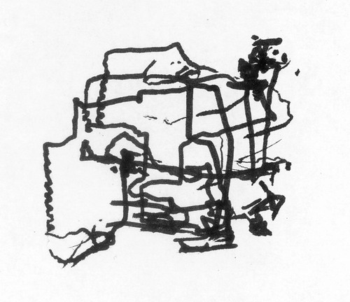
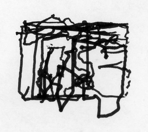
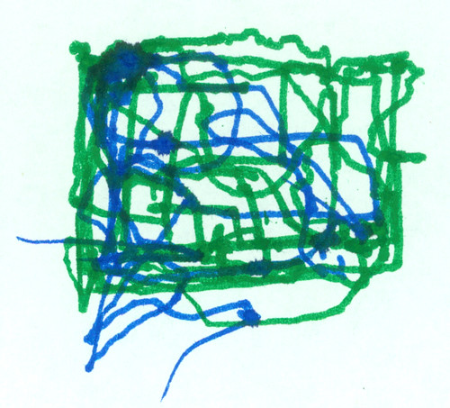
Moments of control and of chaos happened in the process of making each drawing, resulting in an interesting aesthetic contrast between gird-like ordered lines and messily sketchy ones.
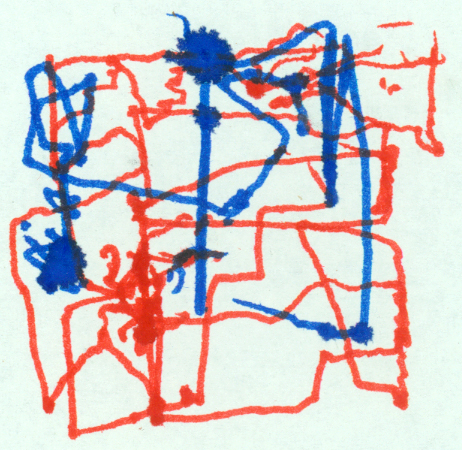
This short video combined from moments taken while making a series of different drawings demonstrates this combination of precision and erratic physicality:
In nearly all of these drawings, I’m attempting to depict the actual machine itself — it being the only thing I can see while also looking at the in-progress drawing. The tiny scale (1.5″ by 1.5″) accentuates the effect of the moments of machine-based surprise, often rendering the drawings illegible.
this is so rad!! did you control it using just one potentiometer?
Thanks, Sarah! I used two pots. One to control each axis: up/down, left/right. Just like a real etch-a-sketch.
Could you attach washer to the pen to keep it more stable?
I’d like to see you draw the outline of the square… just to get a sense of the size of the thing and how much motor control you have.
And then of course, you have to make a web-interface for those controls so I can use it from here. 🙂
There are washers attached to the pen holding it in place. If you look at the first photo of the machine I posted above, you can see a red ring around the pen. There’s one underneath it as well. The trick is that if the pen pushes against the paper too hard, it torques into a funny angle and the motor can’t move it. If it’s not tight enough against the paper, it doesn’t make dark or consistent enough lines.
As far as size goes, most of the drawings I’ve posted take advantage of the full range of motion available, the full 1.75″ by 1.75″. So those drawings should give you a pretty good sense, but I can see the value of making the simple rectangle you’re describing.
For the web interface, you’ll have to wait for my final project for pcomp this semster…
I wonder if the pen wants to be in a sleeve with a spring. That could give it nice steady pressure against the paper, and the sleeve could help it stay straight up-and-down.
Great to hear about your ITP adventures!
How about stacking an extra fork on each of the existing ones, but an inch higher, with a weight attached to the lower part of the pen?
Patrick — I was thinking about doing just that. I think in combination with Devin’s spring suggestion, it might make a big difference.
Pingback: Construir una impresora 2D con un arduino y lectores de CD | El rincón de Zerial