
It was through the service of that same earth that modeling portraits from clay was first invented by Butades, a potter of Sicyon, at Corinth. He did this owing to his daughter, who was in love with a young man; and she, when he was going abroad, drew in outline on the wall the shadow of his face thrown by a lamp. Her father pressed clay on this and made a relief, which he hardened by exposure to fire with the rest of his pottery; and it is said that this likeness was preserved in the Shrine of the Nymphs until the destruction of Corinth.
— Pliny the Elder, Natural History
Where does drawing become photography? Where does either dissolve into touch?
Both photography and drawing take, as their founding myth, Pliny’s story of the shadow made permanent. The light touches the lover’s form which obstructs it, casting a shadow. The daughter touches the shadow and records it on the wall, making a drawing. The father fills the drawing with hardening clay, preserving it as sculpture.
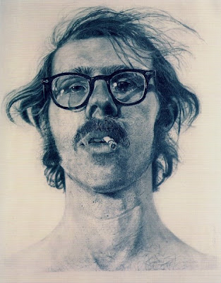
When drawing, a draughstman becomes a kind of camera, catching the light reflecting off his surroundings and recording it in some more permanent medium. His drawings might resemble a photograph quite closely
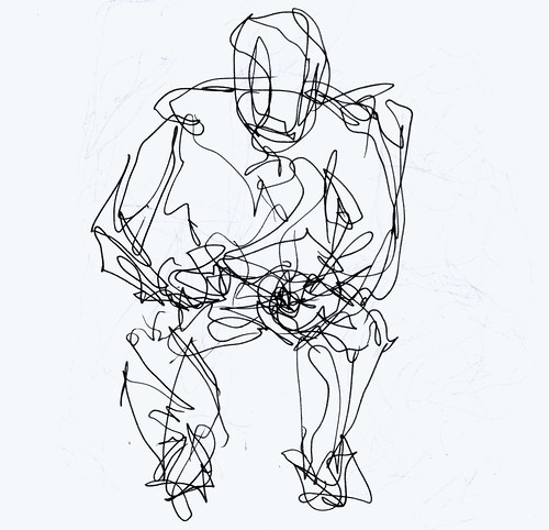
or they might instead deviate from recording the results of monocular perspectival vision to capture some other quality or process:
Conversely, photography itself isn’t always so ‘photorealistic’ now is it? Whether it be Étienne-Jules Marey’s studies of motion,

or David Hockney’s polaroid collages,

or even scientific imagery such as microscopy,

photographers possess at least as wide a range of techniques for recording reflected light as draughtsmen.
So then, what exactly distinguishes drawing from photography?
One possible source of distinction might be this: in most media we call drawing, the light has to pass through the draughtsman’s body before it reaches the recording medium. The image is produced in conversation with the body, by its extension, repression, exaggeration, or focused attention.
The body is not a mere mechanism. Or, more modestly, it is a wildly more complex mechanism than anything else we might call a camera.
Given that, can we imagine a process that would treat the body as a camera? Would the results of such a process count as drawing or photography?
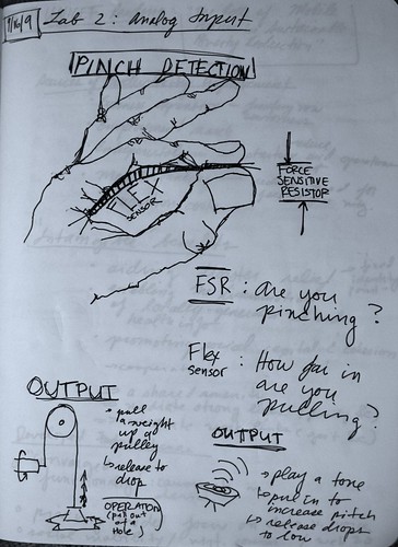
Pinch Control — Laser Drawing
I set out to build a machine that would take the tiny physical gestures that form the basis of conventional drawing and simultaneously amplify and precisely record them.
I began with the Pinch Control gestural interface I’d been developing for making music. I designed this interface to capture the details of any gesture performed with index finger and thumb brought together at the tip; it captures the curve of the index finger and the pressure between the two digits.
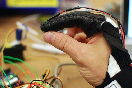
I wanted to increase the fidelity of both of these parameters and also improve the ergonomics of the interface so that it didn’t hamper the natural and fluid movements of the hand. To accomplish this (and on Dano’s advice), I built the two sensors into a single-fingered glove I’d cut out of a batting glove. The flex sensor ran through the fabric of the glove along the back of the index finger; the FSR which captured pressure was embedded in the front of the glove. I then ran the wires down the back of the hand and anchored them at the wrist. The result was that the thumb and palm were completely free of wires, sensors, or restraints of any kind, making for a much freer and more comfortable interface.
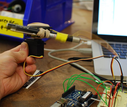
Once I was successfully recording these aspects of the gestural movement, I needed a way to project them back out into visible space in order to make drawings. I wanted a device that would amplify the tiny range of gestural movement as much as possible, filling a wall or large space if possible. To achieve this, I settled on a laser pointer. By taking a long-exposure photograph of the movement of the laser pointer over a surface, I could build up a kind of gesture drawing out of the changes in light created by the small movements of my hand.
I fed the data from the two sensors to a pair of servo motors mounted perpendicular to one another to allow full motion along the x- and y-axes. I mapped the flex sensor to horizontal rotation while the much more sensitive and difficult to control pressure pad controlled the vertical. Here’s some footage of the interface early on before calibration and attaching the laser:
From this you can get a sense of how the interface accentuates small details of the gestural motion. Attaching the laser, of course, wildly increased these exaggerations. In projecting the movements of my hand, the distance between the mounting position of the laser and the wall caused even small changes in angle or rotation to result in large scale swings of the point of light around the room.
Once the laser was mounted, I added one additional detail to the system: I programmed it to sample the position of each motor as fast as possible throughout the course of each drawing. In this way, each drawing would, in addition to the image captured by my camera, leave an additional trace of geometric data from which additional series of drawings could later be created. This geometric data would project the motion of the actual laser onto a perfectly rectangular plane, making visible the transformations and distortions introduced by the space in which the drawing was performed as well as the vicissitudes of the mechanism itself. I also imagined that this data could potentially be used to ‘play back’ the drawing at some future point, by feeding it back to the motor-mounted laser for an additional ‘performance’.
Once I had the device built, I took it into a dark room, hooked up a camera, shut the lights, and made some drawings. Here were some of the results:
![Pinch Control 20090927-214021 [Photo]](http://farm4.static.flickr.com/3496/3961436638_7fddd984e1.jpg)
![Pinch Control 20090927-214021 [Points]](http://farm3.static.flickr.com/2444/3960658857_18c6c1aa4c_o.jpg)
![Pinch Control 20090927-214021 [Lines]](http://farm3.static.flickr.com/2670/3960659131_3e721d81b2_o.jpg)
Pinch Control 20090927-214021 [Photo], [Points], and [Lines] The larger image here is the actual photograph; the other two are different visualizations of the data captured during the making of the drawing: the first displays it as a series of separated points, the second as a continuous line. I decided that the continuous line visualization followed the process of making these drawings — always fluid and gestural by necessity — more accurately.
![Pinch Control 20090927-213921 [Photo]](http://farm3.static.flickr.com/2590/3961435610_63ebc78ab0.jpg)
![Pinch Control 20090927-213921 [Lines]](http://farm4.static.flickr.com/3521/3960659219_147f332c9a_o.jpg)
Pinch Control 20090927-213921 [Photo] and [Lines] Interestingly, when placed in the context of the data visualization, the photographic recording of the drawing beings to look like a detail extracted from amidst the actual movement. It also appears much rounder and more fluid, emphasizing the difference between the continuous recording of light made by the camera and the discrete sampling captured from the sensor data.
![Pinch Control 20090927-213832 [Photo]](http://farm3.static.flickr.com/2425/3960660833_2b7c4f6d82.jpg)
![Pinch Control 20090927-213832 [Lines]](http://farm4.static.flickr.com/3651/3961433492_e05589fa31_o.jpg)
Pinch Control 20090927-213832 [Photo] and [Lines] Another difference between the photographic recording of the drawing and the visualization is that because of the nature of photography, points that are visited repeatedly by the laser tend to glow more intensely in the photographs whereas (at least in this simple Processing sketch) the visualizations reduce that information to the simple question of did the line visit this point or not? This distinction is even more obvious in the final drawing-visualization pair below.
![Pinch Control 20090927-213648 [Photo]](http://farm3.static.flickr.com/2582/3960660165_74bac994a5.jpg)
![Pinch Control 20090927-213648 [Lines]](http://farm3.static.flickr.com/2457/3960659275_282c4bc09f_o.jpg)
Pinch Control 20090927-213648 [Photo] and [Lines]
As a summation, some final notes about process: I’ve included all the source code involved in this project below. It takes the form of three scripts: first, the Arduino program that reads the sensors from the Pinch Control interface and maps it to both the serial output for recording and to the motors to manipulate the laser.
Second is the Ruby program that I ran on the multimedia computer to receive the x- and y-coordinate data from the Arduino and record it for future visualization. You’ll notice that this script and the Arduino firmware coordinate in a ‘serial handshake’ in order to keep the data from coming in smoothly without gaps due to the highly different clock rates of the two machines. Also, I wrote this so that each file generated by this script would be named with a date and time stamp. This allowed me to go back and correlate the data files with the photographs after the fact by looking at the EXIF data from the camera and lining up the times.
Finally, here’s the Ruby program I used to parse the comma-separated coordinate data and generate Processing scripts for visualization. The heart of the matter here is a simple procedure of looping through each pair of x and y readings and outputting a new call to Processing’s line() function in the body of the draw() block.